Evaluation Kit PowerHapTM
Application note
Series/Type:
Evaluation Kit - PowerHapTM Actuator
Date:
Version:
2018-04-26
1.2
Content of header bars 1 and 2 of data sheet will be automatically entered in headers and footers! Please fill in the table and then
change the color to "white". This ensures that the table disappears (invisible) for the customer PDF.
Don't change formatting when entering or pasting text in the table and don't add any cell or line in and to it!
Identification/Classification 1
Evaluation Board - PowerHap™
(header 1 + top left bar):
Identification/Classification 2
Application note
(header 2 + bottom left header bar):
Ordering code: (top right header bar)
TM
Series/Type: (bottom right header bar)
Evaluation Kit - PowerHap actuator
Preliminary data (optional):
Preliminary data
Department:
PPD PI AE/IE PD
Date:
2018-04-26
Version:
1.2
EPCOS AG 2017. Reproduction, publication and dissemination of this publication, enclosures hereto and the information
contained therein without EPCOS' prior express consent is prohibited.
EPCOS AG is a TDK Group Company.
�Evaluation Kit for PowerHapTM Piezo actuators
Preliminary data
1 Contents
1
Contents...........................................................................................................................................................2
2
Introduction ......................................................................................................................................................3
3
4
5
6
2.1
Ordering Code .........................................................................................................................................3
2.2
Content of evaluation driver kit ................................................................................................................4
Installation ........................................................................................................................................................6
3.1
Hardware installation (connector and board diagram) ............................................................................6
3.2
Initialization ..............................................................................................................................................7
3.3
Dimensions of the driver boards ..............................................................................................................8
3.4
Software Installation ................................................................................................................................9
3.4.1
Software Installation ............................................................................................................................9
3.4.2
Software Setup ....................................................................................................................................9
“PowerHapTM Signal Configurator” software description ...............................................................................10
4.1
Choosing the right COM port .................................................................................................................11
4.2
Signal configuration ...............................................................................................................................11
4.3
Configuration for „Push“.........................................................................................................................12
4.4
Configuration for „Release“....................................................................................................................13
Preferred software settings for 2.5G, 7G, and 15G types .............................................................................14
5.1
Typical signal parameter for the 2.5G Type ..........................................................................................14
5.2
Typical signal parameter for the 7G Type .............................................................................................15
5.3
Typical signal parameter for the 15G Type ...........................................................................................16
5.4
Configuration of a *.csv file ....................................................................................................................17
Detailed description of hardware ...................................................................................................................18
6.1
Electrical Description .............................................................................................................................18
6.2
Circuit diagram of driver board ..............................................................................................................18
6.3
External trigger function description ......................................................................................................22
6.4
Parallel operation on one output channel for test purpose ....................................................................23
7
Software revision history list ..........................................................................................................................24
8
Important Notes .............................................................................................................................................25
PPD PI AE/IE PD
Please read Cautions and warnings and
Important notes at the end of this document.
2018-04-26
Page 2 of 25
�Evaluation Kit for PowerHapTM Piezo actuators
Preliminary data
2 Introduction
This evaluation kit was developed to support engineers during their first steps designing applications
with the PowerHapTM piezo actuators for haptic feedback.
This evaluation kit is available in two versions.
The design is not qualified regarding manufacturing and operation over the whole operation
temperature range or lifetime.
The bevaluation kits provided by TDK are intended to be used for functional testing only.
Due to their purpose, evaluation driver kits are not intended to be used by the same procedures
regarding returned material analysis (RMA) and process change notification (PCN) as regular
products.
The board described is an evaluation driver board dedicated for laboratory
environment only. It operates at voltages up to 124V. This board must be
operated by qualified and skilled personnel familiar with all applicable safety
standards.
2.1
Ordering Code
Version 1 was designed to drive up to five PowerHapTM. It can be ordered by using the ordering
code Z63000Z2910Z 1Z 7.
Version 2 can drive a single PowerHapTM actuator at a time. It can be ordered by using the
ordering code Z63000Z2910Z 1Z 1.
.
PPD PI AE/IE PD
Please read Cautions and warnings and
Important notes at the end of this document.
2018-04-26
Page 3 of 25
�Evaluation Kit for PowerHapTM Piezo actuators
Preliminary data
2.2
Content of evaluation driver kit
One channel evaluation kit
Power supply (12VDC / 1A) shipped with two pin connector (Euro connector)
Micro USB cable
One part of each PowerHapTM type (15G; 7G; 2.5G)
USB memory stick
o PC configuration software*
o Documentation
4 pcs female connectors
One channel driver board
Figure 1: PowerHapTM 1-channel driver board
*In case your company policy does not allow the use of USB sticks pls. contact your TDK sales
contact person.
PPD PI AE/IE PD
Please read Cautions and warnings and
Important notes at the end of this document.
2018-04-26
Page 4 of 25
�Evaluation Kit for PowerHapTM Piezo actuators
Preliminary data
Five channel evaluation kit shipped with two pin connector (Euro connector)
Power supply (12VDC / 1A)
Micro USB cable
One part of each PowerHapTM type (15G; 7G; 2.5G)
USB memory stick
o PC configuration software*
o Documentation
8 pcs female connectors
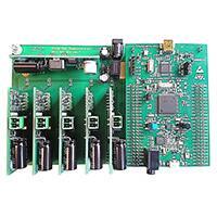
5 channel driver board
Figure 2: PowerHapTM 5-channel driver board
* In case your company policy does not allow the use of USB sticks pls. contact your TDK sales
contact person.
PPD PI AE/IE PD
Please read Cautions and warnings and
Important notes at the end of this document.
2018-04-26
Page 5 of 25
�Evaluation Kit for PowerHapTM Piezo actuators
Preliminary data
3 Installation
The driver boards are designed to drive the different PowerHapTM types of TDK. As described in the picture
above, the main parts on the demonstrator are the base board, the step up converter, the output driver boards
(up to five output driver boards are possible) and the CPU unit.
Configuration software comes with the demonstrator board. With this software, a lot of parameters can be
adjusted (like the shape of the waveform, driving voltage, frequency, etc.) More details can be found in the
software section.
3.1
Hardware installation (connector and board diagram)
The following sections provide an overview of the board including main features, key data, pin
assignment and mechanical dimensions.
Example: One channel driver board
High Voltage Power supply
12 VDC power supply
connector
+
-
Output driver
Slots for additional driver boards
CPU unit
Micro USB
connector
Figure 3: PowerHapTM 1-channel driver board connection diagram
PPD PI AE/IE PD
Please read Cautions and warnings and
Important notes at the end of this document.
2018-04-26
Page 6 of 25
�Evaluation Kit for PowerHapTM Piezo actuators
Preliminary data
3.2
Initialization
After the driver board is powered up an initialization process is running. This takes some seconds. During this
time it is recommended not to press any connected PowerHapTM
The initialization process is finished when the green LED (LD4) on the STM32F407G-DISC1 board is on
The LD4 is located between the blue and the black switch on the board.
LD4 ON: Initialization process
finished
Figure 4: Driver board with control LED between blue and black switch.
PPD PI AE/IE PD
Please read Cautions and warnings and
Important notes at the end of this document.
2018-04-26
Page 7 of 25
�Evaluation Kit for PowerHapTM Piezo actuators
Preliminary data
3.3
Dimensions of the driver boards
8.8 mm
31.7 mm
41.7 mm
Figure 5: Outer dimensions of the baseboard (Length x Width L x W= 160.0mmx100.0mm)
Figure 6: Height of the driver (total height: 41.7mm; height PCB: 31.7mm)
PPD PI AE/IE PD
Please read Cautions and warnings and
Important notes at the end of this document.
2018-04-26
Page 8 of 25
�Evaluation Kit for PowerHapTM Piezo actuators
Preliminary data
3.4
Software Installation
3.4.1 Software Installation
The software will work with Windows 7 versions and higher. For the installation of the software you will
need administrator rights on your computer
USB driver installation
Before connecting the board to a computer, the USB driver for the system must be installed. The
relevant driver can be found on thr USB stick in the folder “USB Driver”
a. For 32 bit Windows versions execute the file “VCP_V1.3.1_Setup.exe”
b. For 64 bit Windows versions execute the file “VCP_V1.3.1_Setup_x64.exe”
c.
Follow the installing instructions on your computer
Installation of the configurator software
a. In the folder “Configurator_V1.2.0.0” execute the file “Setup Feedbacktaster 5-fach.msi”
b. Follow the installation instructions on your computer
c.
A restart of the computer after the software installation is recommended
3.4.2 Software Setup
The software is ready to use after successful installation of the USB driver and the PowerHapTM
Signal configurator. Before opening the PowerHapTM configurator you have to perform the
following steps:
1. Connect the demo board with a micro USB cable to your computer; use the micro USB
port (see also section 3.1 for further details).
2. Connect the piezo PowerHapTM device(s) to the output drivers(s)
3. Power up the demo board by applying 12 VDC
4. Open the PowerHapTM Signal Configurator software on your computer
5. Select the COM-port of the USB connection
6. Click the “Connect” button to establish the USB connection between demo board and
PC
PPD PI AE/IE PD
Please read Cautions and warnings and
Important notes at the end of this document.
2018-04-26
Page 9 of 25
�Evaluation Kit for PowerHapTM Piezo actuators
Preliminary data
4 “PowerHapTM Signal Configurator” software description
Functionality of the PowerHapTM Signal Configurator
Configuration of the feedback signals
Manual trigger
Data transfer via USB
Upload of a signal configuration from a csv file
Saving of the configuration
A software trigger can be given to the
selected output; for the „Push” signal.
The settings of the selected channel are
transmitted to the driver board
The settings of all channels are
transmitted to the driver board
Figure 7: „PowerHapTM Signal Configurator” software detailed
description
A csv file configuration can be
transmitted to the selected channel of the
driver board. Please note that the
parameters from a csv file are not
displayed in the fields of a channel. See
also section 5.4 for further details
With the „Save“ button all adjustments
are saved. When the board is powered
up it comes with these saved values,
otherwise the adjustments are lost when
the system is switched off.
PPD PI AE/IE PD
Please read Cautions and warnings and
Important notes at the end of this document.
2018-04-26
Page 10 of 25
�Evaluation Kit for PowerHapTM Piezo actuators
Preliminary data
4.1
Choosing the right COM port
If there are other evaluation driver boards are connected to your computer you will have the possibility to
choose more than one COM port.
You can find out the right port which is used for the PowerHapTM demonstrator port in the “Control Panel” of
your computer
Control Panel -> Device Manager -> (Ports (COM & LPT))
In this window you can see which COM port is assigned to the PowerHapTM demonstrator board (see picture
below; in that case it is the COM port 3)
„Figure 8 PowerHapTM Signal Configurator “software” COM Port selection
4.2
Signal configuration
The configuration always refers to the selected channel (1 to 5); each channel has its own tab.
For the single channel driver board only channel 1 is functional.
PPD PI AE/IE PD
Please read Cautions and warnings and
Important notes at the end of this document.
2018-04-26
Page 11 of 25
�Evaluation Kit for PowerHapTM Piezo actuators
Preliminary data
4.3
Configuration for „Push“
Amplitude: 5 to 100% (100% correlates to about 100V)
Frequency: 20 to 300Hz
Signal form: Selection among Trapezoidal / sine square wave / Saw tooth
Duty cycle: 35 to 75%; available for the waveform “Trapezoidal”
Pulse count: 1 to 1000; Outputs the adjusted amount of positive voltage pulses to the at set channel
output.
Trigger level: 0 to 12V
In idle state, a voltage level of example 8.4 V is displayed on the according channel. This voltage is
decreased by the generated voltage from the PowerHapTM when it is pressed. When this voltage is
lower than the adjusted trigger level, the haptic feedback is triggered. It is recommended to set the
trigger level about 1 V to 1.5 V below the idle state voltage. The lower the trigger level the harder you
have to press the PowerHapTM to trigger the haptic feedback.
"Delay time: During the time span defined by the delay time the system is not active and will
therefore not detect a force applied to the piezo element. The delay time measurement starts as
soon as the previous actuation mode has finished.
Figure 9: “PowerHapTM Signal Configurator” Push settings
PPD PI AE/IE PD
Please read Cautions and warnings and
Important notes at the end of this document.
2018-04-26
Page 12 of 25
�Evaluation Kit for PowerHapTM Piezo actuators
Preliminary data
4.4
Configuration for „Release“
If the “Release active box” is checked, a second haptic feedback will be triggered when the force from the
PowerHapTM is removed.
Comment: For normal haptic feedback applications we recommend to switch off the “release active” box.
Amplitude: 5 to 100% (100% correlates to about 100V)
Frequency: 20 to 300Hz
Signal form: Selection among trapezoidal / sine square wave / sawtooth
Duty cycle: 35 to 75%; available for the waveform “Trapezoidal”
Pulse count: 1 to 1000; with the pulse count the amount of pulses per trigger event can be chosen.
Release timeout:
If the release of the button is not detected within the adjusted time, no “Release” signal will be given to
the output. After this adjusted time, the board is ready to detect a “push” signal from the button
Release gradient:
When releasing the button, the gradient of the input voltage vs. time is measured by the demo board. If
the voltage change exceeds the adjusted value, the release output signal is triggered. A value of 1
corresponds to a gradient of 0.3 V/s.
Figure 10: “PowerHapTM Signal Configurator” Release settings
PPD PI AE/IE PD
Please read Cautions and warnings and
Important notes at the end of this document.
2018-04-26
Page 13 of 25
�Evaluation Kit for PowerHapTM Piezo actuators
Preliminary data
5 Preferred software settings for 2.5G, 7G, and 15G types
5.1
Typical signal parameter for the 2.5G Type
Figure 11; recommended settings for 2.5G type.
Figure 12: Optional setting: (In case no second pulse is required when releasing the pressure
remove the check mark in the box “Release active”.
PPD PI AE/IE PD
Please read Cautions and warnings and
Important notes at the end of this document.
2018-04-26
Page 14 of 25
�Evaluation Kit for PowerHapTM Piezo actuators
Preliminary data
5.2
Typical signal parameter for the 7G Type
Figure 13: Recommended settings for 7G type.
Figure 14: Optional item: (Normally no second pulse is required when releasing the pressure. In
this case remove the check mark in the box “Release active”.)
PPD PI AE/IE PD
Please read Cautions and warnings and
Important notes at the end of this document.
2018-04-26
Page 15 of 25
�Evaluation Kit for PowerHapTM Piezo actuators
Preliminary data
5.3
Typical signal parameter for the 15G Type
Figure 15: Recommended settings.
Figure 16: Optional item: (In case no second pulse is required when releasing the pressure
remove the check mark in the box “Release active”.
PPD PI AE/IE PD
Please read Cautions and warnings and
Important notes at the end of this document.
2018-04-26
Page 16 of 25
�Evaluation Kit for PowerHapTM Piezo actuators
Preliminary data
5.4
Configuration of a *.csv file
A customized waveform configured via a *.csv file can be transmitted to the PowerHapTM demonstrator
board.
Format of a *.csv file: semicolon is required as separator.
The values of a *.csv file can be changed i.e. with Excel or Notepad
Maximum amount of time / voltage values: 20
Linear interpolation between two “time / voltage” values (see also below diagram).
“ Repetition: how often is the “push” or “release” waveform given to each single output.
Time / voltage columns:
A certain voltage value can be adjusted at a certain time as shown in below table.
The time column defines the duration until the target voltage level (defined in voltage
column) is reached. The example shown in below diagram and table show the total
timeline of voltage levels (“waveform”) which is applied to the PowerHapTM. In the shown
example the total timespan of the defined waveform is 4600µs.
V/%
100
90
80
70
60
50
40
30
20
10
0
0
1000
2000
3000
4000
5000
t/µs
Unit for time: µs
Unit for voltage: V
With the button “Transmit .*csv-file” the values of the selected file will be transmitted to the board
With the “save” button the configuration is stored on the non-volatile memory of the
demonstrator board. This means that after powering up the board this saved configuration is
available
Repetition of the „push“
signal
Means
„push“
Voltage column for the push
signal
time column for
push
Repetition of the „release”
signal
Means
„release“
Voltage column for the push
signal
time column for
release
PPD PI AE/IE PD
Please read Cautions and warnings and
Important notes at the end of this document.
2018-04-26
Page 17 of 25
�Evaluation Kit for PowerHapTM Piezo actuators
Preliminary data
6 Detailed description of hardware
6.1
Electrical Description
Base board
12 VDC power supply:
High voltage power supply:
Output driver:
Slots for additional driver boards:
CPU unit:
unit.
Micro USB connector
6.2
On the base board the different units are installed
Connect a 12VDC power supply to this jack
Step up converter; 124VDC for the output driver are generated
The PowerHapTM actuators are connected to this output stage.5 output
drivers are installed for a 5 channel driver board.
Up to five output driver boards can be driven
A STM32F407G407G-DISC1 evaluation driver board is used as CPU
Changes of the configuration can be done with this interface
Circuit diagram of driver board
Figure 17: STMicroelectronics evaluation driver board STM32F407G-DISC1
Pin Description:
ADC_#1 to ADC_#5:
Via these inputs the system monitors the voltage across the piezo elements
(5 inputs for potentially 5 piezo elements) in order to detect when force is
applied to the piezo element, resulting in a compression (sensing function).
SHDN_#1 to SHDN#5:
Selection of the driver board
DAC_1:
Analogue output, shape of the waveform is given on this output:
PPD PI AE/IE PD
Please read Cautions and warnings and
Important notes at the end of this document.
2018-04-26
Page 18 of 25
�Evaluation Kit for PowerHapTM Piezo actuators
Preliminary data
Signal conditioning of the
analog output
Resistors R8 and R9 not used
5V Power Supply
Figure 18: Schematic of 5V supply; DAC amplifier
PPD PI AE/IE PD
Please read Cautions and warnings and
Important notes at the end of this document.
2018-04-26
Page 19 of 25
�Evaluation Kit for PowerHapTM Piezo actuators
Preliminary data
Figure 19: Schematic of the high voltage power supply module
Resistors R1 to R5 not in use
Figure 20: On this distribution board up to five output driver boards can be placed and controlled
shown with the dashed line on the schematic above
PPD PI AE/IE PD
Please read Cautions and warnings and
Important notes at the end of this document.
2018-04-26
Page 20 of 25
�Evaluation Kit for PowerHapTM Piezo actuators
Preliminary data
Figure 21: Schematic of one output driver board
PPD PI AE/IE PD
Please read Cautions and warnings and
Important notes at the end of this document.
2018-04-26
Page 21 of 25
�Evaluation Kit for PowerHapTM Piezo actuators
Preliminary data
6.3
External trigger function description
Figure 22: There is the possibility to trigger the PowerHapTM with an external signal as
described below.
Input pins on the microcontroller for triggering
Input “PE1”
Trigger on channel 1
Input “PE2”
Trigger on channel 2
Input “PE3”
Trigger on channel 3
Input “PE4”
Trigger on channel 4
Input “PE5”
Trigger on channel 5
Input “PE6”
Trigger on channel 1 to 5 simultaneously; the adjusted waveform of channel 1 is
given to all 5 channels
PPD PI AE/IE PD
Please read Cautions and warnings and
Important notes at the end of this document.
2018-04-26
Page 22 of 25
�Evaluation Kit for PowerHapTM Piezo actuators
Preliminary data
Trigger signal description
With the external trigger signal the adjusted waveform which is adjusted with the “PowerHapTM Signal
Configurator” is given to the output driver. E.g. a trigger on the input PE1 gives an output signal on the output
driver 1.
• A falling edge on the trigger signal (3V to 0V) gives the adjusted “push” signal to the output
• If a “release” signal is adjusted in the “PowerHapTM Signal Configurator”, the release signal is given
to the output with a rising edge on the trigger level “0V to 3V”
• A trigger signal on the input PE6 triggers all 5 channels simultaneously. The waveform given to all
channels is the configured waveform of channel 1
• Voltage level on the input pins on the microcontroller:
• 0V low
• 3V high
• The external trigger and the trigger with the PowerHapTM work in parallel
• If only the external trigger should be used, it is recommended to set the trigger level to 1 V
in the configuration software
• This makes sure that the output cannot be triggered with the sense function of the
PowerHapTM
Important notes when connecting input pins on the microcontroller
•
•
•
6.4
The signal ground (GND) from the trigger source has to be connected to the ground (GND) level of the
microcontroller board
The ground (GND) level must not be connected to earth
The trigger signal can also be applied with a photo coupler with the advantage of a galvanic isolation
between the signal source and the PowerHapTM demonstrator
Parallel operation on one output channel for test purpose
For test purpose, it is a possible to connect more than one PowerHapTM on one output channel. Depending on
the mode of operation (amplitude and frequency of the output signal, type of PowerHapTM) it is listed below how
many parts can be connected.
If two PowerHapTM of the 15G types are connected to one output of the driver, it is recommended to drive it less
than 30 s continuously when the output is adjusted to the maximum frequency of 300 Hz and amplitude of
100%.
15 G type:
7 G type:
2.5 G type:
2 parts on one output channel (f = 300 Hz; amplitude = 100 %)
4 parts in parallel on one channel (f = 300 Hz; amplitude = 50 %)
4 parts in parallel on one channel (f = 300 Hz; amplitude = 100 %)
When multiple pulses are given to the output with two connected 15 G types, please note that the amplitude of
the output voltage will decay with each pulse. The reason for this behaviour is the higher load on the output.
PPD PI AE/IE PD
Please read Cautions and warnings and
Important notes at the end of this document.
2018-04-26
Page 23 of 25
�Evaluation Kit for PowerHapTM Piezo actuators
Preliminary data
7 Software revision history list
Firmware version
1.3.0.2
Revision of the firmware
Date
30.6.2017
remark
--
Configurator version
1.2.0.0
Revision of the PC configurator
Date
30.6.2017
remark
--
The revisions of the firmware and PC configurator software is shown in the bottom of the configurator
software. The firmware is shown when the board is connected.
PPD PI AE/IE PD
Please read Cautions and warnings and
Important notes at the end of this document.
2018-04-26
Page 24 of 25
�Important notes
8 Important Notes
The following applies to all products named in this publication:
1. Some parts of this publication contain statements about the suitability of our products for
certain areas of application. These statements are based on our knowledge of typical
requirements that are often placed on our products in the areas of application concerned. We
nevertheless expressly point out that such statements cannot be regarded as binding
statements about the suitability of our products for a particular customer application. As a
rule, EPCOS is either unfamiliar with individual customer applications or less familiar with them
than the customers themselves. For these reasons, it is always ultimately incumbent on the
customer to check and decide whether an EPCOS product with the properties described in the
product specification is suitable for use in a particular customer application.
2. We also point out that in individual cases, a malfunction of electronic components or failure
before the end of their usual service life cannot be completely ruled out in the current state
of the art, even if they are operated as specified. In customer applications requiring a very high
level of operational safety and especially in customer applications in which the malfunction or
failure of an electronic component could endanger human life or health (e.g. in accident
prevention or life-saving systems), it must therefore be ensured by means of suitable design of the
customer application or other action taken by the customer (e.g. installation of protective circuitry
or redundancy) that no injury or damage is sustained by third parties in the event of malfunction or
failure of an electronic component.
3. The warnings, cautions and product-specific notes must be observed.
4. In order to satisfy certain technical requirements, some of the products described in this
publication may contain substances subject to restrictions in certain jurisdictions (e.g.
because they are classed as hazardous). Useful information on this will be found in our Material
Data Sheets on the Internet (www.epcos.com/material). Should you have any more detailed
questions, please contact our sales offices.
5. We constantly strive to improve our products. Consequently, the products described in this
publication may change from time to time. The same is true of the corresponding product
specifications. Please check therefore to what extent product descriptions and specifications
contained in this publication are still applicable before or when you place an order.
We also reserve the right to discontinue production and delivery of products. Consequently,
we cannot guarantee that all products named in this publication will always be available.
The aforementioned does not apply in the case of individual agreements deviating from the
foregoing for customer-specific products.
6. Unless otherwise agreed in individual contracts, all orders are subject to the current version of
the “General Terms of Delivery for Products and Services in the Electrical Industry”
published by the German Electrical and Electronics Industry Association (ZVEI).
7. The trade names EPCOS, CeraCharge, CeraDiode, CeraLink, CeraPad, CeraPlas, CSMP, CTVS,
DeltaCap, DigiSiMic, ExoCore, FilterCap, FormFit, LeaXield, MiniBlue, MiniCell, MKD, MKK,
MotorCap, PCC, PhaseCap, PhaseCube, PhaseMod, PhiCap, PowerHapTM, PQSine, PQvar,
SIFERRIT, SIFI, SIKOREL, SilverCap, SIMDAD, SiMic, SIMID, SineFormer, SIOV, ThermoFuse,
WindCap are trademarks registered or pending in Europe and in other countries. Further
information will be found on the Internet at www.epcos.com/trademarks.
Page 25 of 25
�